Difference between revisions of "Lock in amplifier"
From emboxit
m (1 revision) |
|
(No difference)
| |
Latest revision as of 07:41, 26 August 2017
Contents
Bentham Instruments
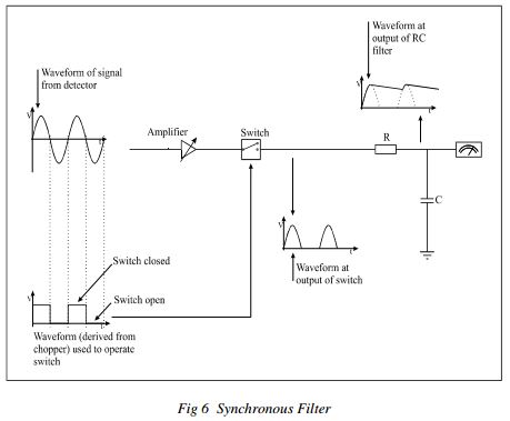
...As before there is circuitry to amplify low level signals, but now there is no tuned filter or
rectifying diode. Instead the amplifier is followed by a switch which is operated by a
waveform derived from the chopper. When the level from the chopper is high the switch is
closed and the output of the amplifier is connected directly to a low pass filter consisting of a
resistor (R) and a capacitor (C). When the output of the chopper is low the switch is open and
no connection is made.
Rectification of the signal occurs when the waveform controlling the switch is exactly in
phase with the ac signal at the input to the switch, hence the sometimes used description,
synchronous rectifier. More importantly when the switch is closed the noise associated with
the signal passes through un-rectified to the low pass RC filter beyond where it is smoothed or
averaged to its mean value of zero.
The device behaves as a bandpass filter and performs the same function as a tuned amplifier
followed by a rectifier but with the following advantages.
1) The effective bandwidth and hence noise rejecting capability of the device is
determined only by the values of the components used in the low pass filter. In fact the
bandwidth is given by 1/4T where T is the time constant1
 of the RC filter. A time
constant of 2.5 seconds will thus give a bandwidth of 0.1Hz which at centre frequency
of 175Hz corresponds to a Q of 1750.
2) The centre frequency of the filter is locked (hence lock-in) onto the chopper’s
frequency. The signal can never drift outside the pass band of the filter.
 8 Bentham Instruments Ltd 225.02
3) Any noise which is present at the output is equally distributed about the mean value
resulting from demodulation of the signal. It does not give rise to a dc level as with
the diode rectifier and increasing the time constant will reduce its’ magnitude.
A Microcontroller Based Digital Lock-In Milliohmmeter
- Described are the waveform capture method, example firmware and hardware designs.This material formed the basis of an article that was first published in the January, 2004 issue of Circuit Cellar magazine.
- A paper that covers similar material more thoroughly than the material presented on this web page was written by Lars E. Bengtsson and submitted to REVIEW OF SCIENTIFIC INSTRUMENTS in 2002. A link to the paper appears below
- A microcontroller-based lock-in amplifier for sub-milliohm resistance measurements Lars E. Bengtsson
Analog Devices
- Synchronous Detectors Facilitate Precision Low-Level Measurements by Luis Orozco
- Use Synchronous Detection to Make Precision, Low Level Measurements by Luis Orozco, systems applications engineer, Analog Devices, Inc. PDF
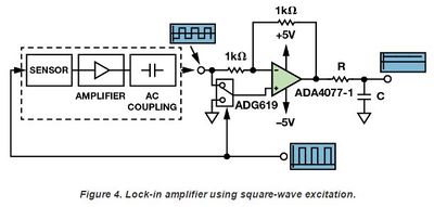
Figure 4 shows an easy way to implement a lock-in amplifier. A microcontroller or
other device generates a square wave excitation that causes the sensor to respond.
The first amplifier would be a transimpedance amplifier for a photodiode,
or an instrumentation amplifier for a strain gage.
The same signal that excites the sensor controls the ADG619 SPDT switch.
When the excitation signal is positive, the amplifier is configured for a gain of +1.
When the excitation is negative, the amplifier is configured for a gain of –1.
This is mathematically equivalent to multiplying the measured signal by the reference square wave.

The output RC filter removes signals at other frequencies, so the output voltage
is a dc signal equal to half the peak-to-peak voltage of the measured square wave.

Although the circuit is simple, choosing the right op amp is important.
The ac-coupled input stage removes most of the low-frequency input noise,
but will not remove the 1/f noise and offset error from the last amplifier.
The ADA4077-1 precision amplifier has 250 nV p-p noise from 0.1 Hz to 10 Hz
and 0.55 µV/°C offset drift, making it an ideal candidate for this application.

A square-wave-based lock-in amplifier is simple, but its noise rejection is inferior
to those using sine waves. Figure 5 shows the frequency domain representation of
square wave excitation and reference signals. A square wave comprises an infinite
sum of sine waves at the fundamental and all odd harmonics.
Multiplying two square waves of the same frequency involves multiplying each sine
component of the reference times each sine component of the measured signal.
The result is a dc signal that contains energy from every harmonic of the square wave.
Unwanted signals that appear at odd harmonic frequencies will not be filtered out,
although they will be scaled down depending on the harmonic they fall in.

Thus, it is important to choose a modulation frequency whose harmonics are not
at the frequency or harmonic of any known noise sources.
To reject line noise, for example, choose a modulation frequency of 1.0375 kHz,
which does not coincide with harmonics of 50 Hz or 60 Hz, instead of using 1 kHz,
which is the 20th harmonic of 50 Hz.

Even with this drawback, the circuit is simple and low cost.
Using a low-noise amplifier and choosing the right modulation frequency
can still result in a great improvement over trying to make a dc measurement
Unclasified
- http://www.phys.utk.edu/labs/modphys/Lock-In%20Amplifier%20Experiment.pdf
- http://hades.mech.northwestern.edu/index.php/Phase-Sensitive_Detection
- http://www.thinksrs.com/downloads/PDFs/ApplicationNotes/AboutLIAs.pdf
- http://electron9.phys.utk.edu/optics507/modules/m10/tn1000.pdf
- http://www.google.gr/url?sa=t&rct=j&q=&esrc=s&source=web&cd=4&cad=rja&ved=0CFoQFjAD&url=http%3A%2F%2Fcourses.washington.edu%2Fphys431%2Flock-in%2Flockin.pdf&ei=LFEzUIaABcTc4QT-tYH4Ag&usg=AFQjCNEhKpT_CIjANxjl1wQHZbyxzWjgMQ&sig2=k7g7jQfik1aMrT_51QsFaw
- http://www.google.gr/url?sa=t&rct=j&q=&esrc=s&source=web&cd=18&cad=rja&ved=0CF4QFjAHOAo&url=http%3A%2F%2Fservv89pn0aj.sn.sourcedns.com%2F~gbpprorg%2Fzine2%2Fmisc%2FSimpleLockInAmplifier.pdf&ei=81IzUJzZMafb4QT5_YHQBA&usg=AFQjCNEbp4ACJdh3hn1mYO34V-kws_-rlg&sig2=xzfyF3yZ-sJvBu73Dz4VxQ
- http://www.edn.com/design/analog/4312612/Compact-four-quadrant-lock-in-amplifier-generates-two-analog-outputs
- http://www.ebay.com/sch/i.html?_nkw=lock-in+amplifier
- http://www.google.gr/url?sa=t&rct=j&q=&esrc=s&source=web&cd=1&cad=rja&ved=0CEkQFjAA&url=http%3A%2F%2Fservv89pn0aj.sn.sourcedns.com%2F~gbpprorg%2Fzine2%2Fmisc%2FSimpleLockInAmplifier.pdf&ei=sFgzUN7HH6Pj4QSX0IGwDg&usg=AFQjCNEbp4ACJdh3hn1mYO34V-kws_-rlg&sig2=SISHCEnHQmrWgn127CP8Og
Fig. 3. A popular experiment to demonstrate how lock-in detection can
recover a small signal buried in noise. When the LED is close to the photodetector,
the signal is large and can be seen directly on the oscilloscope.

When the LED is farther away,
the signal is no longer visible on the oscilloscope, but is easily detected with the lock-in.

