BQ25504
From emboxit
Contents
Overview
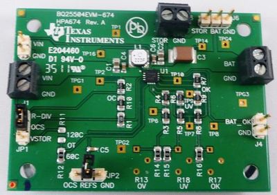
- BQ25504 Nano Power, suitable for WSN
- Maximum power point tracking (MPPT) is implemented in bq25504 in order to maximize the power extracted
from an energy harvester source.
- When operating as a charger, the main storage elements must be connected to VBAT pin. Many types of
elements can be used, such as capacitors, super capacitors or various battery chemistries

TI documentation
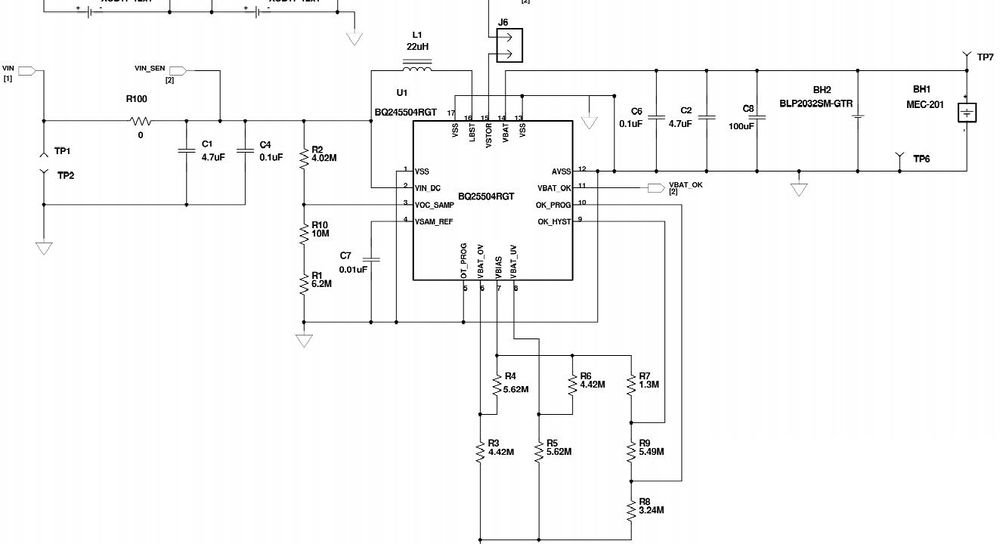
- BQ25504 Ultra Low Power Boost Converter with Battery Management for Energy Harvester App
- Voltage In 0.33 ~ 3.1 V
- Cell Type Capacitor,Lithium Ion, Li-Ion,Super-Capacitor, Thin Film
- Voltage Out 3.1 V
- Current Out 200 mA
- Features Over Voltage Protection Power Good OutputShutdown, Enable, Standby Thermal Protection Under Voltage Protection, Brown-Out
- Component Count + Extras 22 + 10
- Current In 200 mA
- Input Power 400 mW
Purchase
- digikey price $7.35
Cap-xx app note
- A very good presentation:Charging a supercapacitor from a solar cell with a bq25504 PPT energy harvesting IC, CAP-X#
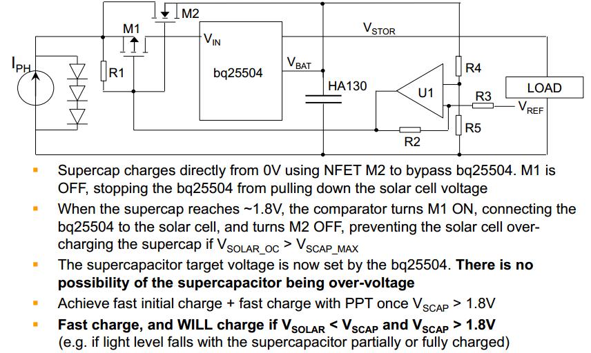
1.When the unit first powers ON with the supercapacitor at 0V, the source of M2 is at 0V,U1 is OFF and R1 turns M1 OFF,
 preventing the bq25504 from operating
2.When VSOLAR > VGSTH of M2, M2 starts to conduct, charging the supercapacitor
3.The resistance across M2 loads the solar cell so its voltage is just above M2(VGSTH) + VSCAP
 so the solar cell provides good charge current in reasonable light
4.When VSCAP=1.85V, the o/p of U1 goes low, turning M2 OFF, and turning M1 ON.
 This enables the bq25504 when the voltage at VBAT> VSTOR_CHGEN,
 so the IC always operates in PPT mode and never in cold start mode
5.Select a low power open drain comparator within-built reference and which operates at a supply voltage down to 1.8V or less.
 In our example, we used a TLV3011, which has a typical quiescent current of 2.8μA and VREF = 1.242V.
 An alternative is MAX9016 with a typical quiescent current of 1μA and VREF = 1.236V
6.Select M2 with the lowest VGSTH possible, with suitable size and gate charge.
 The lower the VGSTH, the faster the supercapacitor will reach 1.85V and enable PPT mode in the bq25504
 We have used an irlm6246, which has typical VGSTHof 0.8V
7.The other components used in slide 9 were: M1=FDV302P, R1 = 1MΩ, R2 = 10MΩ, R3 = 220KΩ, R4 = 680KΩ,R5 = 1.5MΩ.
8.The hysteresis in the circuit means U1 will go low when VBAT > 1.85V and U1 will go open drain when VBAT < 1.77V
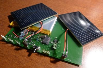
Project Indoor solar energy harvesting
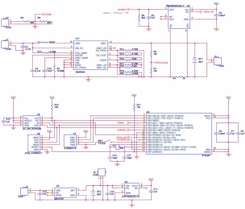
When there is no light, the quiescent current of the harvesting part of the platform is actually
3uA (1uA from the BQ25504 + 2uA from R6&R7)
MAX9934
The MAX1551 li-ion battery charger is here to allow logging battery charge at any point in time
ADP162 LDO 3.3V regulator from Analog Devices has been chosen,
as it has a very low quiescent current (7uA for 1mA load) and a very low dropout voltage (7mV for 10mA load)
Current consumption of the whole circuit is 635uA in sleep mode, which gives me a nice
theoritical 38 days autonomy for the 580mAh Li-Ion batteries
Average harvested energy for this 24h period is 244uW for the BQ25504 and 141uW for the fixed load.
This was during a semi-cloudy / sunny day in mid-december in Switzerland.
The board was approximately 3 meters from the window,
solar panels facing up, with the axis platform > window > south west
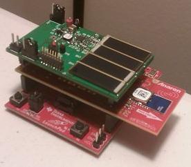
Project Energy Harvesting BoosterPack for LaunchPad
Micropelt
Connected to BQ25504 board
 The output voltage of the TEG can be connected to a voltage booster and power management circuitry,
to step-up the voltage and buffer the energy.
Related articles
